1. RC Airplane Parts

Fuselage – the main body of the RC airplane.
It serves as a housing of the internal components and holds together the outer
parts.
Wings – makes the RC model airplane fly.
This part supports the RC airplane in flight and the size, type, and location
of the wing determines the flight characteristics of the RC airplane.
Aileron – controls the longitudinal axis or
the rolling motion of the wing. It also controls the RC airplane’s direction by
means of banking the wing either in the left or right direction.
Flaps – sometimes added to increase the
lift of the wing and to reduce the runway distance on take-off.
Horizontal Stabilizer – usually located at the tail of the
aircraft. It serves to stabilize it in the lateral axis or to counter act the
up and down motion of the aircraft (or pitch).
Elevator – attached to the horizontal
stabilizer. It controls the up and down motion (or pitch).
Vertical Stabilizer – also located at the tail and
perpendicular to the horizontal stabilizer. It stabilizes the aircraft in the
vertical axis.
Rudder – attached to the vertical stab,
which control the RC airplane in the vertical axis. This mechanism is usually
found in full size aircraft but optional in model aircraft.
Landing Gear – along with the wheels supports the
aircraft on the ground. The two common types are tricycle and the tail dragger.

Two Basic Types of
Landing Gear
Engine,
Propeller & Fuel Tank – is called the power plant. It generates the
thrust to support the aircraft in flight. The engine is located
usually in the front of the aircraft and drives the propeller to generate
thrust. The fuel tank holds the fuel and usually located behind the
engine.
Radio
Equipment – includes the following: servos, receiver (Rx), and Rx
batteries, transmitter (TX).

Three-channel Radio Controlled RC Airplane Components
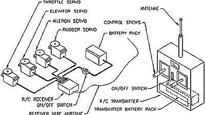
Typical Four-Channel
Radio Control Layout & Components
2. Why & How RC Planes Fly

Airfoil of a Typical RC Airplane
The wings cross-section is called
an airfoil. The forces that acts on the wing of the RC airplane is what
makes it fly. Based on the illustration below, the relative wind passes from
the leading edge to the trailing edge

Illustration of the Forces that Acts on
the Wings
The arrows
represent the direction of air molecules and bubble numbers (1) and (2)
represents the air molecules. The upper camber has a low-pressure area and
the lower camber has a high pressure. As the air passes through an airfoil, it
separates from the leading edge and travels on the upper camber and the lower
camber. The air molecules number (1) and (2) separates from the leading edge
and both should meet on the trailing edge at the same point, at the same time.
This phenomenon is called the law of continuity.
Without the law of continuity it is
impossible for an RC airplane to fly. Because of this, the air molecules on the
upper camber travel faster than the air molecules on the lower camber. In
Bernoulli’s theorem, “as the velocity of air increases, pressure decreases”.
The pressure on the lower camber is greater than the upper camber; the variance
of pressure generates the lift needed by the aircraft.

Three Basic Types of Airfoil
The flat
bottom design is stable on the longitudinal axis and self-correcting tendency
is very ideal for a beginner. The semi symmetrical type is for intermediate
flyers and the symmetrical is for the expert who wants to fly aerobatics .

Wing Span of a Non-Taper Wing
The area of
the wing is very important to know if the aircraft could carry it’s own weight.
There is a certain limit of the total weight of the aircraft, depending on
its wing area, designed speed and type of airfoil. The weight divided by the
total area of its wing span is called wing loading. It is
advisable to keep the weight down, if the weight of the RC airplane exceeds the
recommended weight, the RC airplane needs more airspeed to generate lift.

Forces Acting on an Aircraft in Flight
There are
forces that act on an aircraft in flight, the lift, weight, thrust and drag. To
achieve a stable straight and level flight, these forces should be balanced.
Lift pulls the aircraft up and weight pulls the aircraft down. If weight is greater
than the lift, the aircraft will descend or vice versa. Thrust pulls the
aircraft forward and drag pulls it backwards. When the aircraft is taking-off
the ground or needs to gain altitude, the thrust should be greater than the
drag. As the thrust increases, the lift increases to make the aircraft gain
altitude or off the ground. This is also the reason why there is a recommended
engine size of the aircraft. The engine to achieve flight must provide the
power needed by the aircraft.
3. Stability and Control
All aircraft needs stability and the only way to stabilize an aircraft (if it cannot stabilize itself) is by its control surfaces. But first let us study the airplane’s axis of rotation. The airplane moves on it’s three dimensional axis (see Fig. 9a):
1) “X” axis or the longitudinal axis
2) “Y” axis or vertical axis
3) “Z” axis or lateral axis

Figure 9a : Three dimensional axis of rotation
The aileron controls the longitudinal axis. It serves to stabilize the aircraft by banking and steering left or right (see Fig. 9b). It is a common notion that the rudder in the vertical fin controls the steering of the aircraft. Yes its true, even the Wright brothers used the rudder on their first airplane until they discovered that the aileron is much better. If you have a model with just three channels (rudder, throttle and elevator) it will work just fine. It operates with similar principle but I would suggest that aileron is much better. I remember when I was flying a full size Cessna. It was my first flight and when the instructor let go of the controls and put me in charge, I used to experiment steering the aircraft by its rudder. He said, “Hey, what are you doing?” I said, “I’m steering the aircraft.” Then he told me “Who told you to use the rudder? Use the aileron, you can’t use the rudder for turning.”

Figure 9b : Using aileron on banking and steering the aircraft
Maybe he is not aware that model aircraft can use rudder for turning. But I also don’t know why is it not possible in the full-scale aircraft. Not until I studied Aeronautical engineering that I discovered how those control surfaces and the viscosity of air aerodynamically affects the aircraft. Because the model is much lighter compared to full-size aircraft, rudder is quite effective in steering the aircraft. Unlike the full-size aircraft, because of the viscosity of air, it’s ineffective.
The aileron works by deflecting the air upwards or downwards. Since the airflow is disturbed, drag increases. But the upper and lower camber has two different functions so it will result in two different manners. Disturbing the airflow in the upper camber will create more drag compared to the lower camber. Why? Because the upper camber, as we’ve learned has lower pressure area that creates the lift. If the airflow is deflected upwards, the high-pressure region will leak to the low-pressure region, hence resulting in a loss of lift. Because of the leakage, turbulence will occur in the trailing edge until it reaches the upper camber. This causes more drag than deflecting the air downwards because the upper region, which is the low-pressure area, will not leak on the high-pressure area. Hence, turbulence is minimal (see Fig. 10).
This is why the airplane turns when banking. If you bank the airplane’s wing on the right, it will automatically turn right or vice versa. The drag created on the right wing causes the delay, which gives the left wing more speed.
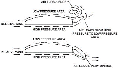
Figure 10 : Aileron deflection of an airfoil
The primary purpose of the rudder is to stabilize the aircraft on its vertical axis. In model aircraft, rudder is utilized for steering. But what is amazing is when you deflect the rudder for example to the left (looking at the back end of the model) the aircraft will turn left and the wing will bank to the left side or vice versa. The explanation is as you turn or rotate the aircraft to the left (along the vertical axis) the right wing travels faster than the left wing. Because the velocity of air is faster in the right wing, more lift is produced. Hence, the result is unbalanced lift that causes the aircraft to bank (see Fig.9c).

Figure 9c : Rudder deflected to left for steering the aircraft
The elevator located on the tail end of the aircraft controls the lateral axis. Its main function is for take-off and landing of the aircraft. It stabilizes the up and down motion of the aircraft. The elevator pushes the tail down when deflected upwards or vice versa and increase the angle of attack of the wing so more lift is produced (seeFig. 9d).

Figure 9d : Elevator deflected upward
The location of the wing will also determine the stability of the aircraft. The most stable type is the high wing configuration on a typical monoplane. The pendulum stability of its wing gives it the natural stability because the weight is under the wing (Fig. 11a). The shoulder wing type is a little touchy because the weight is near the wing (Fig. 11b). The low wing type is the most sensitive to control because the weightis on the upper portion of the wing. That is why dihedral is used to add stability (see Fig. 11c).
Adding another set of wings can increase wing area. This configuration is called a biplane. The wings are decked together, one in the upper part of the fuselage the other on the bottom (see Fig. 11d). This type is quite common in the early days of aviation. In fact the first airplane flown by the Wright brothers the Kitty Hawk was a biplane. The only advantage is the longitudinal stability and drag is a major concern in this design due to the wire braces to support the wings. Triplanes fighters appeared in WWI and was not very popular it is because drag is also a major issue. That is why monoplanes are quite popular until this day because it produces the least drag.

Figure 11a : High wing monoplane

Figure 11b : Midwing monoplane

Figure 11c : Low wing monoplane

Figure 11d : Typical Biplane

Typical Triplane
Other forces that affects aircraft stability
There are other things to consider to stabilize the aircraft. One of them is the three degrees right thrust, which are necessary to stabilize the directional stability of the aircraft. The reason for this is the aircraft has a tendency to turn left when there is no three degrees right thrust (see Fig 12a). The pilot needs to trim the rudder to the right to counteract the left turn tendency. The engine torque against the propeller (see Fig 12b) causes this phenomenon. Most propellers turn in a counter-clockwise motion (front of the airplane). The opposite force is the engine torque, which is clockwise. So the aircraft has a tendency to bank along with the clockwise motion, which is banking to the left. A three degrees right thrust is needed to neutralize the aircraft to fly in a straight path.

Figure 12a : Top View of Model Aircraft Engine with 3 degrees Right Thrust

Figure 12b : Illustration of engine vs. propeller torque
What about the down thrust? It is used to counteract a natural tendency of the aircraft to pitch up or to nose up on a typical high wing monoplane. Since the thrust line is below the wing (see Fig. 13a), there is a tendency for the aircraft to pendulum on its neutral point (see Chapter 4). The engine literally pulls the fuselage up being the neutral point as the pivot point. A three degree down thrust is used to counteract this force to balance it aerodynamically (see Fig 13b). If the thrust line is along the neutral point, like in the mid-wing airplanes (see Fig. 11b) there is no need for down thrust.

Figure13a : Illustration of propeller thrust below the neutral point

Figure13b: Side view of model aircraft engine with 3 degrees down thrust
Landing gear design also has a destabilizing effect if not properly considered. Trainer type RC airplanes always have tricycle landing gear and a tail dragger is usually not recommended. This is not always explained in detail by other beginner books, I also didn’t realize before that this is also important to know for a beginner.
Whenever an aircraft lands, the main gear touches the ground first whether it’s a tail dragger or a tricycle type. Sometimes because of the wind direction an aircraft has to “crab”. Crabbing is a term used because the airplane flies side ways to counteract the wind perpendicular to the landing strip (see Fig 14a). If the aircraft flies straight without crabbing, the aircraft will deviate from its path (see Fig. 14b).

Figure14a: Aircraft crabbing to counteract wind direction

Figure14b: Aircraft deviates from straight path in a crosswind
Because of this, landing a tail dragger is not as easy as we thought. The entire weight of the aircraft is behind the main gear so the momentum is pushing the aircraft instead of pulling it (see Fig.15a). There is no inherent stability in tail dragger unlike the tricycle type. In a tricycle type, the weight is concentrated in front of the main landing gear (see Fig.15b).
The momentum is pulling the aircraft so this is more stable because there is no tendency for the aircraft to tip over when landing and crabbing at the same time. The main gear will just drag and pull the aircraft to a straight path when the wheels strike the ground.

Figure15a : Tail Dragger in a Crosswind Landing
Figure15b: Tricycle Type in a Cross Wind Landing
4. Weight and Balance
We had a brief lesson on how weight affects the aircraft in flight. Because gravity affects the aircraft weight, it is of utmost importance to keep the weight to a minimum. Also, it is important to determine the distribution of weight. Although the aircraft has normal or below the recommended weight, we need to achieve stability for the aircraft to fly properly. If not, the aircraft is hard to control, wh ich may result in unnecessary crash. The distribution of weight is essential to balance the aircraft. Since majority of the aerodynamic forces acts on the wing, it plays a major role in controlling the aircraft.
Looking at the cross-section of the wing, the aerodynamic center is the pivot point of the lateral axis (see Fig 16a). The center of gravity is where all the aircraft weight is concentrated which must be near the aerodynamic center to achieve stability. Since the airplane has two sets of wings (main and tail wing) there are two aerodynamic centers to be considered. The combination of two aerodynamic centers is the neutral point ( see Fig. 16b ). If the center of gravity is way behind the neutral point, the aircraft is called tail-heavy which might result in stalling. If its located too far forward, nose-heavy will result and it will be too hard for the aircraft to gain altitude (see Fig. 16b).
Figure 16a : Aerodynamic center of an airfoil

Figure 16b : Neutral Point of Wing and Horizontal Stabilizer

In a full-size aircraft, the center of gravity determination has to be calculated. The arm or the distance of the load (or cargo) multiplied by the weight is called the moment (remember physics?). The fulcrum or the pivot point is the suggested center of gravity location of the aircraft. The moments of the two sides should be equal so as to balance the aircraft (see Fig. 17a). Since our model aircraft is miniaturized, all we need to do is to balance the aircraft with our fingers on the recommended location of the center of gravity. Based on the example illustration ofFig. 17b, the C.G. (or center of gravity) location is 2 inches from the leading edge.
Figure 17a : Illustration of weight and moments

In model aircraft, the distribution of weight depends on the location of the radio equipment installed. Because they are the last thing to be installed and does not affect much the aerodynamic characteristics of the aircraft The servos, batteries and receivers should be located in such a way that the aircraft will balance on the center of gravity. The engine location was already designed on most plans or kits available so there is not much we can do about it. The best thing to do is before permanently installing the equipment is to arrange it temporarily with a tape then balance the aircraft. The model should already be completely built (engine & fuel tank installed, the airframe is already wrapped with monokote,etc). When the desired location is known, then you can permanently install the radio equipment.
Figure 17b : Balancing model airplane by hands

5. Power Plant
The aircraft powerplant consists of all the accessories needed by the aircraft to produce thrust. It consists of the engine, propeller, fuel tank, spinner, fuel tubing and other accessories that are directly related for the power plant to function (seeFig.18). The model aircraft commonly utilizes the internal combustion engine and electric motors for thrust. Let us first tackle the internal combustion type (or I.C.E.).
Figure 18 : RC aircraft power plant components for internal combustion engine (I.C.E.)

Usually the model aircraft use three different types of internal combustion engines with regards to the fuel they use.
1) Glow engine – engine that uses methanol for fuel and castor oil for lubricant. The igniter is called the glow plug, shaped like a miniature spark plug but uses coil for burning the fuel and air mixture (see Fig.19). Power source for the glow plug is 1.5volts NiCad (Nickel Cadmium) battery or dry cell with high ampere. Usually 75% methanol and 25% castor oil is the fuel mixture. Castor oil readily mixes with methanol unlike the petroleum based motor oil. But for more speed, nitromethane is added depending on the type of aircraft flyer desire (e.g. pylon racing, sport flying or pattern flyer). This type of engine can either be a four-stroke or a two-stroke engine (see Fig.20a & Fig.20b).

Figure 19 : Typical two cycle glow engine
2) Diesel engine – This type engine use kerosene for fuel (jet engine fuel) and with some additive for easy combustion. It burns fuel and air mixture by means of compression in the combustion chamber unlike the glow engine that utilize glow plug to burn the fuel and air mixture. It has more torque than the glow engine so it can swing larger propellers.
3) Gas engine – Gas engines are commonly used by larger RC airplanes because this type has larger displacement. It uses ordinary unleaded gasoline and petroleum based motor oil. You can compare its size with an ordinary handheld chainsaw.
If you are not very familiar with internal combustion engine you may ask, what is the difference between four strokes and two-stroke engine? A four-stroke engine (seeFig. 20b) burns the fuel and air mixture in the combustion chamber more efficiently compared to a two-stroke engine (see Fig. 20a). It is because the two cycle engine as illustrated in Figure 20a, the fuel and air mixture from the crankcase goes to the combustion chamber and the burned mixture are exhausted at the same time so some of the raw fuel is mixed to the burned fuel and exhausted. Fuel is wasted because the inefficient combustion. Unlike the four cycle which the: 1) Intake, 2) Compression, 3) Combustion & 4) Exhaust are four separate cycles which are more efficient because the fuel is completely burned and exhausted before taking in fuel and air mixture.
Figure 20b : Event cycle of a four stroke engine

Figure 20a : Event cycle of a two stroke engine

Figure 21: Electric power plant components

In the past flying electric was not very popular because of the weight penalty of the batteries. But today, there are many who prefer flying with electric motors because of the technological breakthrough. Compared with internal combustion engine, starting is easy, no mess because of the castor oil emitted by the engine, quiet & no need for fuel. The only limitation I perceive is the shorter flying time and it is not as powerful as the internal combustion engine. We don’t need brute force to fly so I think as long as it is strong enough to carry its own weight; there is no problem. Having extra battery packs can solve the limited flying time by charging it alternately after the first one is exhausted.
"IN FINAL WORDS"
As a beginner, we are choosing a high-wing, constant chord (straight wing) and tricycle type landing gear so that we can concentrate on the other controls. These features already have inherent stability as we have tackled before in our research.
Materials are also a major consideration for a model aircraft. The secret for it to fly successfully is to build it light and strong. Traditionally, balsa wood was the first choice because of its strength to weight ratio and very easy to cut, sand or carve. Because the airframe is consisting mainly of balsa, repair was possible and easier unlike the plastic or foam materials. Other materials are combination of foam core wings covered with balsa skins, molded plastic fuselage and fiberglass fuselage. The covering for bare balsa frame is usually an iron-on plastic called “monokote”. It is a strong mylar film coated with pigmented adhesive on one side.
Covering with monokote only need a handy iron to fasten the film to the airframe. After the plane is covered, just apply heat to shrink the film to remove the wrinkles and sags. It is far easier to apply than the traditional silk and dope. The combination of silk and dope provides added torsional strength but heavier compared with mylar film. It also needs an experienced and skillful builder because the total weight will depend on the hobbyist’s skill and it should be built as light as possible.
Figure 23a : Typical model aircraft structure

No comments:
Post a Comment